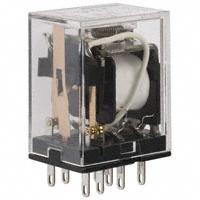
Electromechanical
Relays
General-purpose Latching Relay
MYK
Magnetic Latching Relay Ideal for Memory
and Data Transmission Circuits
• Double-winding latch system that holds residual magnetism.
• Changes due to aging are negligible because of use of special
magnetic materials, thus ensuring long continuous holding time.
• Little change in characteristics such as contact follow, contact
pressure, etc., throughout its long life.
• Excellent vibration/shock resistance.
• Easy monitoring of ON/OFF operation thanks to the built-in operation indicator mechanism.
• Same outline dimensions as the MY Miniature Power Relay.
Ordering Information
■ List of Models
Contact form
Plug-in/solder
terminal model
MY2K
DPDT
PCB terminal
model
MY2K-02
■ Accessories (Order Separately)
Connecting Sockets
No. of poles
Front-connecting Socket
Screw terminals
Back-connecting Socket
Solder terminals
Wire-wrap terminals
PCB terminals
Without Relay
Hold-down Clip
PYF14A-E
PYF14A
PYF14-N
PY14
PY14QN
PY14-02
With Hold-down
Clip
---
PY14-Y1
PY14QN-Y1
---
Note: Refer to the MY Datasheet for detail information on the Relay Hold-down Clips and Relay-mounting Sockets.
General-purpose Latching Relay
MYK
A-67
�Specifications
■ Coil Ratings
Rated voltage
Set coil
Rated current
50 Hz
AC
DC
Reset coil
Resistance
Rated current
60 Hz
56 mA
50 Hz
72 Ω
39 mA
Resistance
Mustreset
voltage
Max.
voltage
% of rated voltage
Power
consumption
(Approx.)
Set coil
60 Hz
38.2 mA 130 Ω
12 V
57 mA
24 V
27.5 mA 26.4 mA 320 Ω
18.6 mA 18.1 mA 550 Ω
50 V
14.0 mA 13.4 mA 1,400 Ω
3.5 mA
3.4 mA
3,000 Ω
100 V
7.1 mA
5,400 Ω
3.5 mA
3.4 mA
3,000 Ω
12 V
110 mA
110 Ω
50 mA
235 Ω
24 V
52 mA
470 Ω
25 mA
940 Ω
6.9 mA
Must-set
voltage
80%
max.
80%
max.
110%
Reset
coil
0.6 to 0.9 0.2 to 0.5
(60 Hz)
(60 Hz)
1.3 W
0.6 W
Note: 1. For AC models, the rated current values are half-wave rectified current values measured with a DC ammeter.
2. The rated current and coil resistance are measured at a coil temperature of 23°C with tolerances of +15%/–20% for AC rated current and
±15% for DC rated current, and +15% for DC coil resistance.
3. The AC coil resistance values are for reference only.
4. Performance characteristic data are measured at a coil temperature of 5°C to 35°C.
■ Contact Ratings
Item
Resistive load (cosφ = 1)
Rated load
3 A at 220 VAC, 3 A at 24 VDC
Rated carry current
3A
Max. switching voltage
250 VAC, 125 VDC
Max. switching current
3A
Max. switching power
660 VA, 72 W
Failure rate* (reference value)
1 mA at 1 VDC
*Note:
Inductive load (cosφ = 0.4) (L/R = 7 ms)
0.8 A at 220 VAC, 1.5 A at 24 VDC
176 VA, 36 W
P level: λ60 = 0.1 x 10⁻⁶/operation
■ Characteristics
Contact resistance
50 mΩ max.
Set time
Time:
Reset time
AC: 30 ms max.; DC: 15 ms max.
Min. pulse width:
AC: 60 ms.; DC: 15 ms.
Time:
AC: 30 ms max.; DC: 15 ms max.
Min. pulse width:
AC: 60 ms.; DC: 15 ms.
Max. operating frequency
Mechanical: 18,000 operations/hr
Electrical: 1,800 operations/hr (under rated load)
Insulation resistance
100 MΩ min. (at 500 VDC)
Dielectric strength
1,500 VAC, 50/60 Hz for 1 min (1,000 VAC between contacts of same polarity and between set and reset
coils)
Vibration resistance
Destruction: 10 to 55 to 10 Hz, 0.5 mm single amplitude (1.0 mm double amplitude)
Malfunction: 10 to 55 to 10 Hz, 0.5 mm single amplitude (1.0 mm double amplitude)
Shock resistance
Destruction: 1,000 m/s2
Malfunction: 200 m/s2
Endurance
Mechanical: 100,000,000 operations min. (at 18,000 operations/hr)
Electrical: 200,000 operations min. (at 1,800 operations/hr)
Ambient temperature
Operating:
Ambient humidity
Operating: 5% to 85%
–55°C to 60°C (with no icing)
Weight
Approx. 30 g
Note: The data shown above are initial values.
A-68
General-purpose Latching Relay MYK
�Electromechanical
Relays
Engineering Data
AC
inductive
load
(cosφ =
0.4)
DC resistive load
DC inductive load
(L/R = 7 ms)
Endurance
Endurance (x103 operations)
AC resistive load
Endurance (x103 operations)
Switching current (A)
Maximum Switched Power
5,000
110 VAC resistive load
220 VAC
resistive load
1,000
500
30 VDC resistive
load
10
5,000
500
10
Switching current (A)
Switching voltage (V)
110 VAC inductive load
(cosφ = 0.4)
1,000
220 VAC
inductive load
(cosφ = 0.4)
30 VDC inductive load
(L/R = 7 ms)
Switching current (A)
Dimensions
MY2K
2.6
Ten, 1.2-dia. holes x 2.2 elliptic holes
0.5
28 max.
6.3
0.5
36 max.
21.5 max.
6.4
MY2K-02
2.6
Mounting Holes
(Bottom View)
13.2
4.4
3.5
4.3
0.5
4.1
28 max.
6.3
36 max.
4
6.35
12.65
6.3
3.75
Ten, 1.3-dia. holes
21.5 max.
Note: Dimensional tolerances
are ±0.1 mm.
General-purpose Latching Relay
MYK
A-69
�Terminal Arrangement/Internal Connections (Bottom View)
AC Model
DC Model
Use at 220 VAC
R
Rs: 7.3 kΩ 3 W
Rr: 14.3 kΩ 1 W
Note: 1. Resistor is for ampere-turn compensation and is
incorporated in the Relay rated at 50 VAC or above.
2. Pay attention to the polarity of the set and reset coils,
as incorrect connection of positive and negative terminal will result in the Relay malfunctioning.
When using the Relay rated at 110 VAC at a supply voltage of 220 VAC, be sure to connect external resistors
Rs and Rr to the Relay.
If the supply voltage is applied to the set and reset coils
at the same time, the Relay will be put in the set state.
ALL DIMENSIONS SHOWN ARE IN MILLIMETERS.
To convert millimeters into inches, multiply by 0.03937. To convert grams into ounces, multiply by 0.03527.
Cat. No. J013-E1-02
A-70
In the interest of product improvement, specifications are subject to change without notice.
General-purpose Latching Relay MYK
�
很抱歉,暂时无法提供与“MY2K AC120”相匹配的价格&库存,您可以联系我们找货
免费人工找货